Assembly Drawing
JohnsonMiller , 04-15-2017, 02:12 AM
Hi,
In Assembly Drawing where do you put the component identifier, inside it or outside? please have a look to screen shot, which form do you recommend?
BR,
In Assembly Drawing where do you put the component identifier, inside it or outside? please have a look to screen shot, which form do you recommend?
BR,

robertferanec , 04-16-2017, 11:48 AM
On the assembly layer we always put reference designator inside the component for two reasons:
- you clearly see which designator belongs to which component
- if we placed designators outside of component, in very busy areas (where components are placed close to each other) there would not be space to place designators ... only to place them far away from the component and then it would not be clear what designator is for what component
JohnsonMiller , 04-16-2017, 11:25 PM
Thank you Robert,
Frankly, I have doubt about usage of this plots! BOM along pick&place contain all required information, why we need to generate assembly plots?
BR,
Frankly, I have doubt about usage of this plots! BOM along pick&place contain all required information, why we need to generate assembly plots?
BR,
mairomaster , 04-18-2017, 02:07 AM
I always do it just out of habit and because I've automated it and it's not a big effort. However, I find it quite useless for most of the designs.
Sometimes it can perhaps be useful when debugging a board which doesn't have silkscreen designators, to have the assembly drawings printed so you have an idea which component are you looking for.
I have the designators inside the courtyards. I am using AdjustDesignators2 Altium script to format/centre them.
robertferanec , 04-18-2017, 02:49 PM
Our assembly house always uses assembly drawings. I guess, it's for their people to see where specific components are located (e.g. if they do some manual placement or if they are checking placement).
JohnsonMiller , 04-19-2017, 10:45 PM
Thank you Robert and Mairomaster,
Mairomaster:
"I am using AdjustDesignators2 Altium script to format/centre them."
I currently have format/center issue, can you explain how to do formating?
BR,
Mairomaster:
"I am using AdjustDesignators2 Altium script to format/centre them."
I currently have format/center issue, can you explain how to do formating?
BR,
mairomaster , 04-20-2017, 01:44 AM
I normally use the following settings:
You can set the minimum and maximum allowed size of the designators.
In Layer Options, you can chose the reference for the component size. I am using the courtyard mechanical layer (also used in the assembly drawings) for the purpose. According to the component size determined by the selected layer primitives, the script automatically adjusts the font size of the designators.
In Designators to include, I am modifying only the mechanical designators (the silk screen ones are usually arranged by hand to fit between the components).
The script basically rotates the designators so they are either 0 or 90 degrees according to the orientation of the component, sets the font to True font, adjusts the font size according to the size of the footprint and centres the designators. The only drawback is that the overall component bounding rectangle is used to centre the designators. In some cases this leads to not that perfect alignment, because of none-symmetrically primitives outside of the component body (for example silk screen markings or none-symmetrical component body which extends beyond the courtyard). In such cases you might need to modify those by hand. In the majority of the cases it's alright though.

JohnsonMiller , 12-20-2017, 10:45 AM
Hi Guys,
The default assembly drawing include component designator, I need an assembly drawing with component's comment field, or values in deed. Is there any possibility to print assembly drawing with comment field instead of designator?
BR,
The default assembly drawing include component designator, I need an assembly drawing with component's comment field, or values in deed. Is there any possibility to print assembly drawing with comment field instead of designator?
BR,
robertferanec , 12-21-2017, 10:45 AM
I have not try it, but you should be able to find the comment field in the "dot" parameters:

JohnsonMiller , 12-22-2017, 06:39 AM
Hello Robert,
Yes, got it and working. Thank you.
BR,
Yes, got it and working. Thank you.
BR,
JohnsonMiller , 02-08-2020, 01:21 AM
Hi Guys,
Assembly house usually asks about assembly drawing, when I use the default setting in Altium, the output is not satisfactory and they always complaining and call for more info! So, my question is what information we should include in assembly drawing?
Regards,
Assembly house usually asks about assembly drawing, when I use the default setting in Altium, the output is not satisfactory and they always complaining and call for more info! So, my question is what information we should include in assembly drawing?
Regards,
cagri.saglam , 02-10-2020, 12:03 AM
Hi,
There is a good video from by @robertferanec: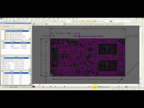 . You can check it.
If you continue to take calls from your supplier/customer, you should try to get some informations that what you should give into assembly drawing. Then, we can look at how we apply them into drawings.
There is a good video from by @robertferanec:
If you continue to take calls from your supplier/customer, you should try to get some informations that what you should give into assembly drawing. Then, we can look at how we apply them into drawings.
robertferanec , 02-11-2020, 01:34 AM
How does your assembly drawing looks? What they are asking about?
Usually we only deliver component outline with reference designator inside + polarity or pin 1 marking + fitted / not fitted highlight. If needed we can add a note about special soldering requirements, but usually that is enough. We also generate View with tracks visible, so it is easier to find specific components - but I am not sure if they use it (we generate it because we use that drawing a lot)
I attached the files, so you can see them. They are from our open source project OpenRex: https://www.imx6rex.com/open-rex/


JohnsonMiller , 02-28-2020, 01:25 AM
Regarding Assembly Drawing, I still have a fundamental question. In pick-and-place file, placement is described in full detail, why we still need to provide these drawings?
robertferanec , 02-28-2020, 07:31 AM
Pick and place file is mostly to feed up the assembly machine. Assembly drawing is for people.
JohnsonMiller , 02-28-2020, 12:26 PM
Exactly! Since people not doing pick-and-place, assembly drawing sounds useless! unless I missing a point.
JohnsonMiller , 02-28-2020, 12:45 PM
And I got a problem, in my component library, a mechanical layer is used to specify the detail of each component. When I create assembly drawing using an output job, Altium prints mechanical data on both prints and does not care that component is either on top or bottom layer. How we can force prints to make difference and show mechanical data based on the layer that component is placed?
robertferanec , 03-02-2020, 08:30 AM
Exactly! Since people not doing pick-and-place, assembly drawing sounds useless! unless I missing a point.
How we can force prints to make difference and show mechanical data based on the layer that component is placed?
JohnsonMiller , 03-02-2020, 01:14 PM
Still, soldering TH by hand? I thought it is done by some robots!
Thank you very much! got it.
- you need to create layer pair. This will help: https://youtu.be/L36KicrU45Q?t=1335
JohnsonMiller , 03-02-2020, 01:35 PM
- you need to create layer pair. This will help: https://youtu.be/L36KicrU45Q?t=1335
JohnsonMiller , 03-03-2020, 05:01 AM
Any help regarding that Tab?
robertferanec , 03-03-2020, 08:26 AM
@JohnsonMiller for AD17 and older, this video can help "Altium Designer – How to Create Assembly Drawing Layers": https://welldoneblog.fedevel.com/201...rawing-layers/
JohnsonMiller , 03-05-2020, 01:33 PM
Thank you Robert, with your help I managed to build a decent assembly drawing; hopefully, both human and the machine can now understand it.
PS- I moved to AD20, and I see that a problem which I once complained about is gone. It was a slow reacting and refreshing schematic viewer,
PS- I moved to AD20, and I see that a problem which I once complained about is gone. It was a slow reacting and refreshing schematic viewer,
JohnsonMiller , 03-11-2020, 03:27 AM
Hi Guys,
Shall we mirror the bottom layer?
The Altium's initial setting is normal, or let's say top-view. But I have been asked to mirror the view.
Shall we mirror the bottom layer?
The Altium's initial setting is normal, or let's say top-view. But I have been asked to mirror the view.
robertferanec , 03-11-2020, 12:49 PM
Interesting. I do not mirror layers for PCB manufacturing. In case your PCB manufacturer really needs to mirror them, they can easily do it by themselves.
However what you may need to mirror is text on the bottom layer. In Altium you can Flip the board (I do not have access to Altium right now, but you will easily find the Flip View command somewhere in the menu) - that will show you the view as you would be looking at the bottom side of your real PCB - double check if everything looks ok there, especially text.
PS: Only the situation when I needed to mirror a layer was when I was making PCB at home and wanted to have the black ink directly touching copper layer
JohnsonMiller , 04-11-2022, 08:39 AM
In the Assembly Drawing, what information the manufacturer is expecting from our board? Which layers should be included?
Can we use Draftsman output instead of Assembly Drawing?
Can we use Draftsman output instead of Assembly Drawing?
robertferanec , 04-11-2022, 09:17 AM
Yes, you can use Draftsman. This may help: https://www.youtube.com/watch?v=W21dORx5ceI&t=1514s
Usually you may want to show component outline and designator. But I often also create a special assembly drawing which also shows top and bottom layer so it is easy to find location of specific components on PCB.
This may help: https://youtu.be/tEJtXHKzW44
Usually you may want to show component outline and designator. But I often also create a special assembly drawing which also shows top and bottom layer so it is easy to find location of specific components on PCB.
This may help: https://youtu.be/tEJtXHKzW44
qdrives , 04-12-2022, 02:39 PM
First off, for assembly it is not the question "which layer". That is for fabrication.
I create two kinds of assembly drawing / documentation. One is extended documentation while the other is more for visual inspection to see where each component is.
I have receive feedback from fabricators nor EMS companies on this documentation.
Other resources:


I create two kinds of assembly drawing / documentation. One is extended documentation while the other is more for visual inspection to see where each component is.
I have receive feedback from fabricators nor EMS companies on this documentation.
Other resources:
mtswan , 08-30-2022, 09:17 AM
@qdrives - do you know if the AltiumLive 2017 live video (part of the second link you shared) is posted anywhere?
qdrives , 08-30-2022, 01:54 PM
@mtswan I do not know if the Altium Live 2017 presentations were recorded as is was an in person event.
Julie Ellis has presented one in 2022 too. The video is here: https://resources.altium.com/p/commo...ltiumlive-2022
For drafstman there is also this video: https://resources.altium.com/p/docum...ltiumlive-2022
Julie Ellis has presented one in 2022 too. The video is here: https://resources.altium.com/p/commo...ltiumlive-2022
For drafstman there is also this video: https://resources.altium.com/p/docum...ltiumlive-2022
Use our interactive Discord forum to reply or ask new questions.