My dead projects with hi speed signals
hitech95 , 06-18-2019, 02:07 PM
Hi,
I'm a hobbyst and I like to play with electronics.
I don't like to build clocks and simple stuff but I love to hack and create devices that are more complex. (Dammit)
Watching the latest vides on Youtube I wanted to contribute with my sh!tty schematics and pcb boards files.
Last summer I started the development of a SBC it was based around the Allwinner A33.
Ths SBC should be the Main Board of my FCThermostat project an IOt enabled Smart thermostat. It should combine a thermostat and a smart speaker inside a small package that can be embedded in a wall. (The dimensions of the wall box it should contain the device: https://images-na.ssl-images-amazon....tL._SX466_.jpg)
Here a fiew more information on the steps I've done so far:
https://hackaday.io/project/159654-f...red-iot-device
(Please keep in mind that the SBC design was made using Circuit Maker so no X-Signal, and Length matcing wasn't done due to the tool limits. The idea was to export the project and continue with another EDA but the PCB pricing was a huge problem so i cancelled the development of this specific design, i'll use a off the shelf SOM and i'll design a carrier board around the SOM i'll pick.
Some components are still not placed. As said it is a dead project so schematic polishing and the full PCB is also not done/completed.)
If you think that I'm crazy check out the next project!
The second project I'm working on is a board addon for my chromebook (An Acer C720P). The idea is to substitute an SD Card IO Board with a more advanced one:
The Chromebook is quite old but it's good for my needs, a friend of mine told me: "Hey the kensington slot is quite similar to USB-C" and than we started to think how we could implement a USB-C into the chromebook.
Why the chromebook? Easy:
The board i'm creating would replace the IO Board in the left in the following photo:
The main plan is to create a castellated board to place on top (or bottom) of the mainboard with a custom shape to connect the PCI-e testpoint to a single FFC/FPC connector. From there a flat flex cable will connect the new IO Board to the mainboard. Power wires will be routed separately using wires. (Not perfect for my standsrds, maybe in future I'll design a new Mainboard for that based on some ARM SoC)
For more info about this chromebook, take a look:

Please note that this project is still WIP and I'm working on the schematic right now. I also have started the design of the PCB to see if the available space was enought to place all the required components!
My only concern so far is how to transfer the pcie-e signal safely between the CPU and the IO board! (I was looking for some shielded FFC cables used for HDMI, I know that the bast way would be SATA wires but I don't have the thickness available)
Have a nice day,
Hitech95
I'm a hobbyst and I like to play with electronics.
I don't like to build clocks and simple stuff but I love to hack and create devices that are more complex. (Dammit)
Watching the latest vides on Youtube I wanted to contribute with my sh!tty schematics and pcb boards files.
Last summer I started the development of a SBC it was based around the Allwinner A33.
Ths SBC should be the Main Board of my FCThermostat project an IOt enabled Smart thermostat. It should combine a thermostat and a smart speaker inside a small package that can be embedded in a wall. (The dimensions of the wall box it should contain the device: https://images-na.ssl-images-amazon....tL._SX466_.jpg)
Here a fiew more information on the steps I've done so far:
https://hackaday.io/project/159654-f...red-iot-device
(Please keep in mind that the SBC design was made using Circuit Maker so no X-Signal, and Length matcing wasn't done due to the tool limits. The idea was to export the project and continue with another EDA but the PCB pricing was a huge problem so i cancelled the development of this specific design, i'll use a off the shelf SOM and i'll design a carrier board around the SOM i'll pick.
Some components are still not placed. As said it is a dead project so schematic polishing and the full PCB is also not done/completed.)
If you think that I'm crazy check out the next project!
The second project I'm working on is a board addon for my chromebook (An Acer C720P). The idea is to substitute an SD Card IO Board with a more advanced one:
- Add an PCIe USB 3.1 Host controller
- Add USB-A 3.1 to replace the available 2.0
- Add USB-C with PD and Acessory Audio
- Keep the previous functionality
The Chromebook is quite old but it's good for my needs, a friend of mine told me: "Hey the kensington slot is quite similar to USB-C" and than we started to think how we could implement a USB-C into the chromebook.
Why the chromebook? Easy:
- We have the schematics, you can find them on the web for free. (Query: Quanta Computer ZHN)
- The EC Firmware is opensource so if I have to hack into that I have the source code
- The BIOS/EFI is also OpenSource and I already managed to enable back a couple of USBs and PCI-E lines
- The Mainboard have a NGFF slot (Key B) PCI-e unpopulatedand around the CPU there also a secondary PCI-e line not used but with testpoints!
- I'ts one of the fiew chromebooks that have a replacable SSD, with the modified firmware by the community I'm able to run Linux and Windows 10.
The board i'm creating would replace the IO Board in the left in the following photo:

The main plan is to create a castellated board to place on top (or bottom) of the mainboard with a custom shape to connect the PCI-e testpoint to a single FFC/FPC connector. From there a flat flex cable will connect the new IO Board to the mainboard. Power wires will be routed separately using wires. (Not perfect for my standsrds, maybe in future I'll design a new Mainboard for that based on some ARM SoC)
For more info about this chromebook, take a look:
Please note that this project is still WIP and I'm working on the schematic right now. I also have started the design of the PCB to see if the available space was enought to place all the required components!
My only concern so far is how to transfer the pcie-e signal safely between the CPU and the IO board! (I was looking for some shielded FFC cables used for HDMI, I know that the bast way would be SATA wires but I don't have the thickness available)
Have a nice day,
Hitech95
Paul van Avesaath , 06-18-2019, 11:37 PM
i have used some Molex cables for PCIe before, but again, you wont like the price..
there are ways of doing the matched length in altium without xSignals.. just make a excell spreadsheat and fill in the numbers..
it takes a bit more time, but defenitly doable..
I cannot acces the links from my work (its all shielded) but will do so later..
there are ways of doing the matched length in altium without xSignals.. just make a excell spreadsheat and fill in the numbers..
it takes a bit more time, but defenitly doable..
I cannot acces the links from my work (its all shielded) but will do so later..
hitech95 , 06-19-2019, 04:32 AM
I shared the project for the video series of "How to Draw Schematic" & "Review of a PCB Layout". I've learnt so much thanks to the videos from Robert and I would like to contribute with my hobby s!itty designs. (BTW i'm not an electonic engeneer, I'm a Computer Science guy. I've studied electronic by myself)
About the molex connector, the problem is that I need to fit evrything inside the chromebook chass and the space is limited. I have no idea how those would work. I have seen dodgy pcie extenders using cheap ribbon cables, i have to extract the signals from the mainboard test points and than route them for 15/20CM.
Yea I wasn't able to upload the files directly to the forum, so I had to find a host ... I don't have/use dropbox & co..
I was using Circuit Maker for the SBC, now it's a dead project. (I would move the project to altium to add the length matching and the last touches but the pcb price (800€+) is out of my available finances. The A33 also in EOL and it's quite hot for my needs. I will look forward for a somaller SOM, maybe something based on IMX. (SO far I've seen that they support Android and they should run quite cooler, I need to measure the ambient temperature and I don't want a 50°C+ nearby CPU altering the measurements, and yes I've put cut slots to prevent this)
A bit of more info are here: https://www.eevblog.com/forum/projec...for-usb3-pcie/
robertferanec , 06-19-2019, 09:10 AM
- Oh, no single description in the FC Front 
- But Peppy looks better. Well done, I see improvements!
For specific advice, the best is to say a little bit more about what you would like to connect and attach some links to resources, otherwise people have to download your project, open it and try to search and understand what you are trying to achieve. For example:
- when you say "My only concern so far is how to transfer the pcie e signal safely between the CPU and the board!" ... if I understand right, we are talking about replacement of a SD Card IO Board in a Chromebook, right? Is there only one version of chromebook? Or is there a specific version of chromebook and SD Card you have in mind? Do you have schematic / pinout of this specific SD Card IO Board?
- also I am not really sure what this means "My only concern so far is how to transfer the pcie e signal safely between the CPU and the board! " ... does it mean PCIE is not on the SD Card IO Board connector, and you are trying to find a way how to bring it to your board? Do you have any ideas where from?
Maybe take some photos and show what you are trying to do ..?
PS: Here are the schematics of projects if anyone would like to have a look:
hitech95 , 06-19-2019, 12:24 PM
Thanks, I'm tring to improve each time.
Yea I'll edit the post to add a fiew more infos.
Yes I'll have to take the PCIE signals from the CPU testpoints. (If i'll fail in taht I have a NGFF key B soket available)
Thanks for the upload, I think that I don't have the permissions to add atachements.
EDIT: I've added the details to the first post!
robertferanec , 06-21-2019, 12:54 AM
I'll have to take the PCIE signals from the CPU testpoints.
M.2 (NGFF) would be maybe the way to go .. but still you would need to figure out a lot of things. Connecting PCIE through a cable is not so simple (you may need to design an adapter). I have done some FLEX PCIE expanders, they worked ok, and I know there are some PCIE cables, but you need to use a good quality cables. Some PCIE cables already exist - so I would google for them and tried to figure out how to fit them into the system.
Maybe some ideas (?): https://www.google.com/search?q=m.2+...wrdlXBcf4zITM:
hitech95 , 06-22-2019, 01:27 AM
The idea is to create a board like this, and use the testpoints:
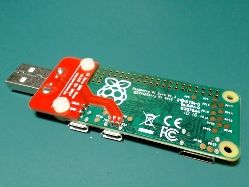
In this way I could have the best possible differential pairs (from the testpoints), from that board i would attach a cable to the IO expander.
That cable looks quite thick, I was thinking something like that
https://www.google.com/search?q=m.2+...WZulVHWlKoLjM:
If I got it right the PCI-e and the HDMI have the same diff-impedence, my idea was from this:
https://www.google.com/search?rlz=1C...Mt5o9QUnPhkhM:
Paul van Avesaath , 07-03-2019, 02:19 AM
yes the impedance is the same, however the HDMI has a driver for it to drive longer length cable. PCIe in this case does not, since it is on a Pi.
so even if you would manage to do this, the testpoint are probably not matched in length or evenly spaced in loaction... (i would hope so but do not believe it) you will have added skew in you lanes.. so do not think you will on speed spec of PCIe in that case..Also make 100% sure taht GND is connected properly.. SI will be terrible if not done right.
so even if you would manage to do this, the testpoint are probably not matched in length or evenly spaced in loaction... (i would hope so but do not believe it) you will have added skew in you lanes.. so do not think you will on speed spec of PCIe in that case..Also make 100% sure taht GND is connected properly.. SI will be terrible if not done right.
Use our interactive Discord forum to reply or ask new questions.