MicroSD schematics and footprint
shihanlin9 , 08-21-2020, 05:23 PM
Hi All,
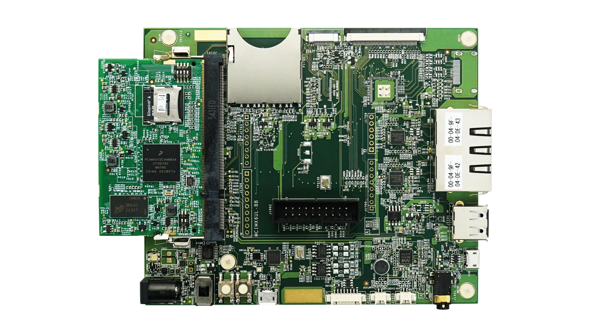
I'm drawing schematics of a board and want to add a microSD connector to the board. Apparently there's 8 pins/fingers on the microSD card, but connectors has more than 8 pins. Take an example, DM3AT-SF-PEJM5 has 14 pins on the footprint. My understanding is 8 pins are electrically connected to the board/soc and the remaining are used to fix this connector to the board, is this correct? Also I've seen on reference design that the remaining pins are connected to the ground, I wonder should we do the same or we should just leave them as floating?
I'm drawing schematics of a board and want to add a microSD connector to the board. Apparently there's 8 pins/fingers on the microSD card, but connectors has more than 8 pins. Take an example, DM3AT-SF-PEJM5 has 14 pins on the footprint. My understanding is 8 pins are electrically connected to the board/soc and the remaining are used to fix this connector to the board, is this correct? Also I've seen on reference design that the remaining pins are connected to the ground, I wonder should we do the same or we should just leave them as floating?
Lakshmi , 08-21-2020, 11:23 PM
Yes, You can connect those to GND.
Also, you can use the card detection pins, to detect or to turn on the SD Power supply only when card is detected.
Have a look at this for reference footprint:
https://www.snapeda.com/parts/DM3AT-...DM3AT-SF-PEJM5
Also, you can use the card detection pins, to detect or to turn on the SD Power supply only when card is detected.
Have a look at this for reference footprint:
https://www.snapeda.com/parts/DM3AT-...DM3AT-SF-PEJM5
robertferanec , 08-24-2020, 06:18 AM
@shihanlin9, I would like to add. We are using microSD card in our open source projects. You can download full Altium files to see how we did that or you can even copy it. For example it is used here: https://www.imx6rex.com/open-rex/
shihanlin9 , 09-10-2020, 01:35 AM
Hi Guys, thanks for the suggestions, that's really helpful. I was planning to simply ignore the card detection pin in my initial design, then I revisited the open-rex design and tried to add that pin, then I realize two things:
1. People need to be really careful with the microSD hinge since each vendor implement the CD pin in different way, for example for DM3AT-SF-PEJM5 it closes the switch when card is inserted where for the one used in open-rex it's the other way.
2. I'm using i.MX6ULZ chip in my design and I would like to use UART1(for serial downloader) or SD1 for internal boot device. According to the iomux config during boot time, seems SD1 is using UART1 pin for card detection function. Does that means UART1 and SD1 are mutually exclusive during boot time? Is it ok to simply ignore the CD in for SD1 and just leave it for UART1?


Lakshmi , 09-10-2020, 03:48 AM
You can use UART1_RTS for Card detection.
For serial Downloader/Console you can just use UART1 Tx & RX either through USB UART Converter OR UART Header on your board.
Have a look at the reference design on the NXP website for iMX6ULZ for better understanding.
For serial Downloader/Console you can just use UART1 Tx & RX either through USB UART Converter OR UART Header on your board.
Have a look at the reference design on the NXP website for iMX6ULZ for better understanding.
Use our interactive Discord forum to reply or ask new questions.
