LCD Track Layout
sukhvirdhillon , 05-28-2020, 04:57 AM
I am looking for help with an issue we are facing with an LCD panel. We are not sure if it is a software issue or a hardware issue and would appreciate a bit of guidance.
We are using a 800 x 480 pixel screen in DPI (RGB) mode and seem to have a random line that seems to scan across the screen as can be seen in the attached images and video. Horizontal lines are unaffected by this. We are not sure if it is a layout issue or a firmware one. To rule out a hardware issue, we are unsure if the traces for this should all be the same length (I can’t seem to find a definitive answer). The lengths of all the traces are shown below:
DISPLAY_VSYNC = 49.64mm (Frame synchronising signal for DPI)
DISPLAY_HSYNC = 47.46mm (Line synchronising signal for DPI)
DISPLAY_DOTCLK = 52.99mm (Dot clock signal for DPI)
DISPLAY_DE = 51.14mm (Data Enable Line)
DISPLAY_DB0 = 46.76mm (DB0 - DB21 = IM£ IM@ IM1 IM0 Interface)
DISPLAY_DB1 = 46.02mm
DISPLAY_DB2 = 43.01mm
DISPLAY_DB3 = 42.29mm
DISPLAY_DB4 = 40.14mm
DISPLAY_DB5 = 38.10mm
DISPLAY_DB8 = 38.87mm
DISPLAY_DB9 = 37.44mm
DISPLAY_DB10 = 37.40mm
DISPLAY_DB11 = 37.61mm
DISPLAY_DB12 = 37.50mm
DISPLAY_DB13 = 37.48mm
DISPLAY_DB16 = 37.56mm
DISPLAY_DB17 = 37.49mm
DISPLAY_DB18 = 37.24mm
DISPLAY_DB19 = 37.61mm
DISPLAY_DB20 = 38.41mm
DISPLAY_DB21 = 36.18mm
DISPLAY_RESET = 79.31mm (Hardware Reset)
DISPLAY_CSX = 75.37mm (Chip selection signal)
DISPLAY_RD = 74.57mm (Read Signal)
DISPLAY_SCL = 70.97mm (Write Signal)
DISPLAY_RS = 69.79mm (Register selection signal)
DISPLAY_SDA = 69.08mm (Serial Data input pin)
Thank you.


robertferanec , 06-01-2020, 01:40 AM
I am not sure what picture you are sending out, but this looks to me like data are not interpreted the right way. This can be problem for several reasons e.g. wrong synchronization, wrong data order, wrong color data interpretation, wrong format, .....
You need to connect oscilloscope to your display interface. Measure frame and line and pixel clock - by sure timing is correct (compare it with display datasheet). Once you set that correctly, you should see a stable not repeating picture ... if not, be sure controller is sending out right format of RGB data (there are several different formats)
You need to connect oscilloscope to your display interface. Measure frame and line and pixel clock - by sure timing is correct (compare it with display datasheet). Once you set that correctly, you should see a stable not repeating picture ... if not, be sure controller is sending out right format of RGB data (there are several different formats)
sukhvirdhillon , 06-01-2020, 01:49 AM
Hi Robert,
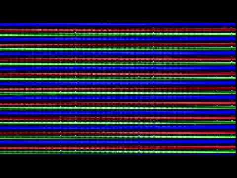
Thanks for the reply and we will investigate further. Would a layout issue cause this? Or is it more likely to be a firmware issue? The image is a test image of RGB lines to see where the noise issues were. You can see the noise issues in the images attached below.
Thanks for the reply and we will investigate further. Would a layout issue cause this? Or is it more likely to be a firmware issue? The image is a test image of RGB lines to see where the noise issues were. You can see the noise issues in the images attached below.


robertferanec , 06-06-2020, 01:33 AM
I am not sure in what direction you are drawing the picture ... is this picture rotated by 90 degrees? If yes, it looks to me like display is sometimes picking up the end of line sync with offset of 1 pixel - wrong line edge setting?. If picture is not rotated and these are columns, then it would look like the picture would be stored like that in memory.

sukhvirdhillon , 06-06-2020, 02:32 AM
Hi Robert. The picture is indeed rotated by 90 degrees as it is a portrait screen we are using in landscape mode. I’ll get my co-founder to check the line edge setting and get back to you.
love your courses by the way. Bought Fedevel courses a few years back and taught me a great deal about Altium. Keep up the great work.
love your courses by the way. Bought Fedevel courses a few years back and taught me a great deal about Altium. Keep up the great work.
sukhvirdhillon , 06-06-2020, 03:05 AM
Also, I got an email which had the following quote from you, but only part of it. I can’t seem to see the rest of this answer. Can you please repost?
“Honestly, this doesn't seems to me as a noise on display interface. Notice, that once the line is moved, it is consistently moved. This looks to me more like”
“Honestly, this doesn't seems to me as a noise on display interface. Notice, that once the line is moved, it is consistently moved. This looks to me more like”
Comments:
robertferanec, 06-08-2020, 02:58 AM
just ignore this, it was my original answer, I edited it when I noticed, that the display is maybe rotated.
sukhvirdhillon , 06-08-2020, 12:24 PM
Thanks Robert. Maybe you could make sense of this... We put a scope on the DOTCLK lines on our own board and also on the Raspberry Pi Compute module 3 development board (Pin 3 = GPIO 0) and get the results shown in the first image - voltage ranges from 1.25V to 2.1V. The second image shows the scope results on the Raspberry Pi 3 DOTCLK line (Pin 27 = GPIO 0) - ranges from 0.8V to 2.5V. Neither are the 0-3V3 we would expect, however the Raspberry Pi 3's 2.5V is over the high voltage threshold for the display driver. As far as we’re aware there’s no additional circuitry on the signal path in either case. Crucially for our application the max voltage observed on the CM Dev Board (~2.1V) is below the 2.3V logic-high threshold for our display driver. The mean is ~1.6V on both boards, which looks correct for a 3.3V signal. Any ideas on what could be causing this difference?


robertferanec , 06-12-2020, 01:04 AM
I do not know what your clock speed is, but some 100MHz oscilloscopes may not be able to show you the correct waveform of 50MHz square signal:
Have a look here:
"Entry level scopes will often have a maximum bandwidth of 100MHz. They can accurately show the amplitudes of sine wave signals up to 20MHz."
https://www.mouser.com/pdfdocs/Tektr..._consider1.pdf
Have a look here:
"Entry level scopes will often have a maximum bandwidth of 100MHz. They can accurately show the amplitudes of sine wave signals up to 20MHz."
https://www.mouser.com/pdfdocs/Tektr..._consider1.pdf

Use our interactive Discord forum to reply or ask new questions.