About length tuning skew for differential pairs in Altium
Ralvb78 , 08-30-2018, 04:55 AM
Hello
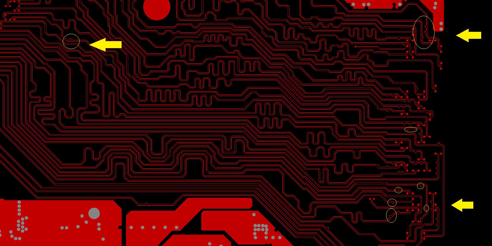
Currently im routing a PCB card with lots of differential pairs folding these at 45° (mainly running at 250 Mbps except 4 of these running at 1.25 Gbps), I've heared that we must compensate differential skew every time when we folds, I have didn't see this before, (never heard it either), but I must to say that even experienced in RF, I'm new routing high speed digital designs, I have taken a look at many application notes on internet but they aren't clear at this point, they are not conclusive. However, looking at demosntration PCB board (see attached figure), It seems that the skew length matching is made at the ends of these lines.
I'd like to know If these partial compensation of skew is mandatory with a well known rule of thumb, and in this case, how to compensate already routed differential pair in Altium when the cumulated skew caused by folding exceeds some limit. I can measure the partial length of routed segments when routing, but I have not found the way to measure once both ends are connected, in these condictions I find too hard to match the cumulated skew in already routed differential pair, I just cant match a differential pair at the ends once routed.
Thanks in advance
Paul van Avesaath , 08-31-2018, 05:21 AM
The reason for compensation at the bends is that your commen mode voltage in the diffpair is compensated. not the skew directly. skew can be compensated at the the receiver side. but i have done both in years of high speed routing and so far it worked fine. for your signal speeds 1.25Ghz either is fine but officially i would recommend compensating near the bends for the bend itself and do the rest at the receiver side.

robertferanec , 09-01-2018, 03:10 AM
One goal of this compensation is to achieve that the edges of the signal travels together. So, you need to be aware from what point the signal starts, where it goes .. and if there are some places, where one of the signals (positive / negative) starts travelling ahead of the other signal, you need to compensate the length.
Usually the compensation is done at the beginning of signal (where the pads are located in different places) and then at the beginning of each layer. If needed, you can also compensate when the skew shift occurs. Just be aware what is beginning (where transmitter is) and what is the end of the signal (receiver end).
Usually the compensation is done at the beginning of signal (where the pads are located in different places) and then at the beginning of each layer. If needed, you can also compensate when the skew shift occurs. Just be aware what is beginning (where transmitter is) and what is the end of the signal (receiver end).
Paul van Avesaath , 09-05-2018, 04:07 AM
are you sure about the location of the serpentine at the beginning? not at the receiver side?
I prefer the local compensations, as long as you start of with a symetrical exit and start point so route those first then it is just a matter of preference were you compensatie a multilane system..
one way of keeping the BGA pins symetrical and be able to switch postitive an negative lines without any issue is using the attached exit strategy
also keeping bends the same will keep the overall length the same between the positive and negative lanes.
by keeping the skew to a minimum the "eye" of the signal will have a crossing in the middle giving the less chance to fail when jitter is added in the design.


robertferanec , 09-12-2018, 02:46 AM
According to design guides, the serpentine should be as close as possible to the place of the distortion. I usually do it at beginning of each layer, because to calculate how much distortion was made when lines were bended is not easy. In design guides, you will also read, that for high speed signals, this compensation needs to be done on every layer and the reason are the signal edges (the moment when signal is changing level for example from low to high or from high to low). As I explained before, signal edges should be travelling together (one of the reasons doing this is, that the noise around the place where edges are travelling is same, but opposite between negative and positive line, so the noise between these lines can cancel each other and it can be helpful for EMC / EMI)
Use our interactive Discord forum to reply or ask new questions.